Facilities
Details about the flow facilities and the measurement techniques available in the lab are as follows:
1. FLOW FACILITIES:
Prof. Ekmekci's research group has two main flow facilities: a large-recirculating water channel for aerodynamic tests and an anechoic wind tunnel for acoustic tests.1.1 Water Channel:
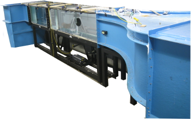
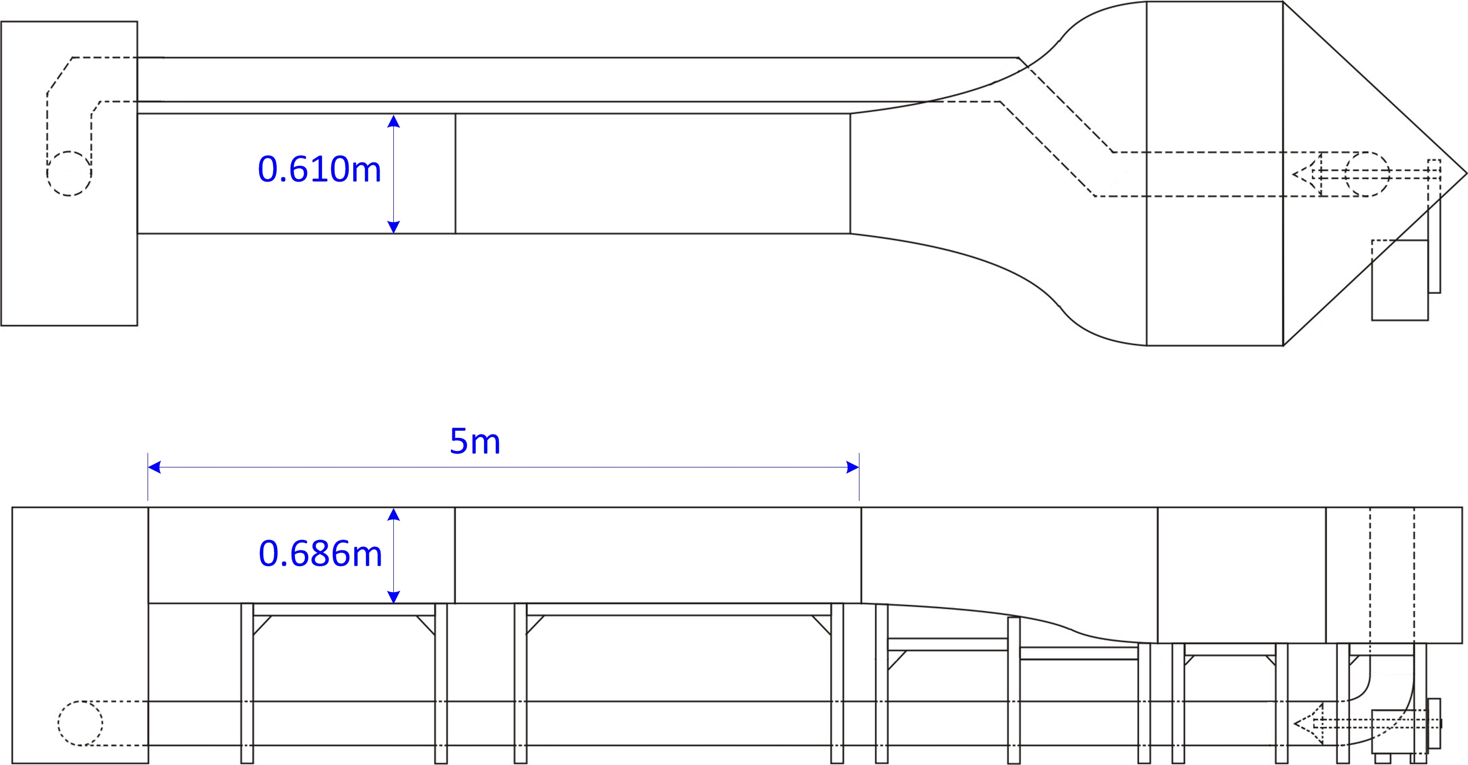
This is a recirculating facility, continuously provides a uniform flow along its 5-m long test section. The walls of the test section are made of Plexiglas material to allow optical access to the flow. This facility can operate in free-surface mode (with no top covers) or as a closed tunnel (using top covers). It is known that compared to a wind tunnel flow facility, the water facilities have the advantage of slowing down the flow dynamics are thereby enable the capture and time- resolved analysis of highly unsteady flow behavior. This facility is therefore used to simulate the flow fields around scaled models of various bodies, including cylinders, landing gears, automobiles, ahmed bodies, bridge models, micro air vehicles, etc.The technical details of this facility can be summarized as follows:
Tunnel Type:
Recirculating Water Channel-Free-surface channel (removing the top covers)
-Tunnel (using top covers)
Test Section Details:
Width: 0.610 mHeight: 0.762 m (in free-surface channel configuration)
0.686 m (in closed tunnel configuration)
Length: 5 m
Speed Range:
0.03 m/s - 0.78 m/sMaximum Reynolds Number:
Re = 780,000 per meter @ T = 20CRe = 880,000 per meter @ T = 25C
(Water temperature is controllable using a thermocouple and a tankless water heater)
Turbulence Level:
< 0.4% @ 0 - 0.66 m/s< 1.3% @ 0.66 m/s - 0.78 m/s
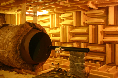
1.2 UTIAS Anechoic Wind Tunnel:
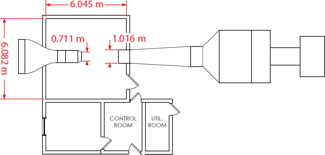
This facility is used to conduct acoustic tests. It is an open jet wind tunnel. The open jet is enclosed within the anechoic chamber.Technical details are as follows:
Tunnel Type:
Open jet, Eiffel type wind tunnelOpen jet enclosed within anechoic chamber
Test Section Details:
Circular jet: 0.711 m diameter.Circular collector: 1.016 m diameter
Length: 2.776 m
Anechoic Room:
Floor Plan: 6.045 m by 6.082 mHeight: 2.36 m
Fibreglass Acoustic Wedges
Speed Range:
10 m/s - 60 m/sMaximum Reynolds Number:
Re = 4,107,500 per meter @ ISATurbulence Level:
< 1%2. EXPERIMENTAL SYSTEMS AND TECHNIQUES:
2.1. Laser-Based Diagnostic Tools:
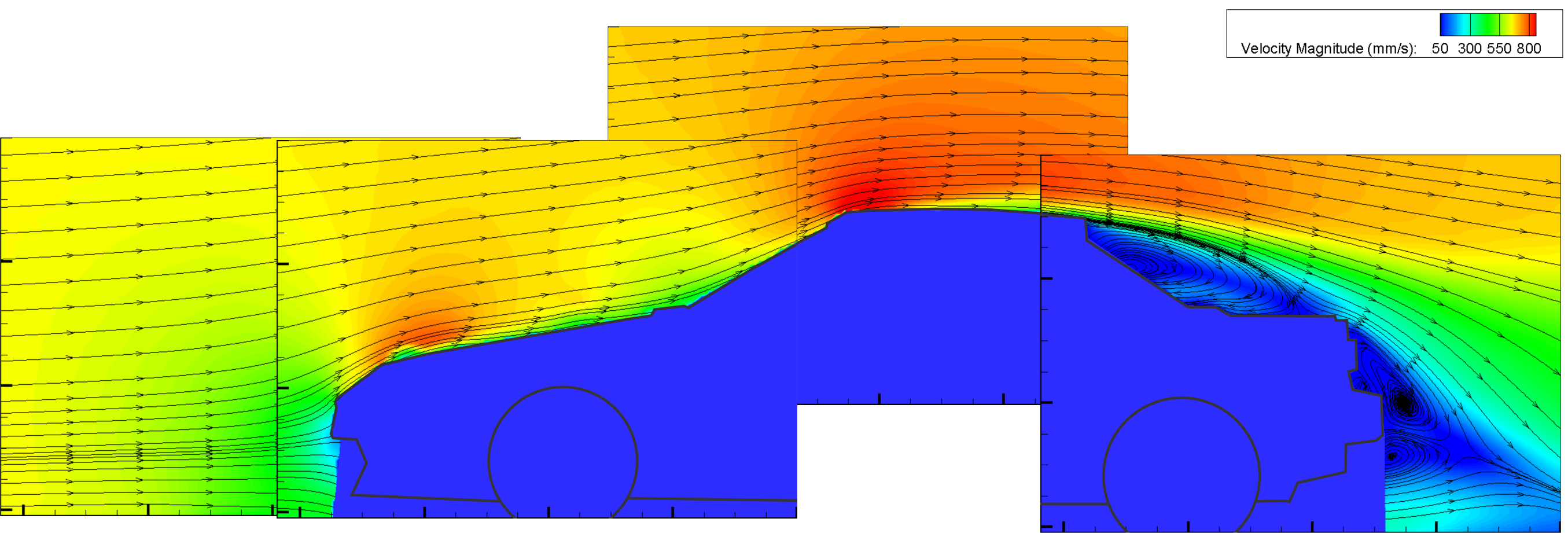
2.1.1. Particle Image Velocimetry (PIV):
The PIV system provides a non-intrusive laser optical intrusive technique to make successive measurements of velocity fields over any planar region of interest in the flow. The acquisition rate of this system is 14.5. During the analyses, this velocity data is used to calculate other flow features, such as, vorticity, frequency spectra of velocity fluctuations, streamlines, the energetic of the dominant flow structures, etc.As an example, the flow field acquired via PIV around a car model is shown below (contours of velocity magnitude and streamline topology are shown overlapped).
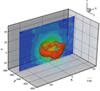
2.1.2. Volumetric 3-Component Velocimetry (V3V):
The V3V system allows measurements of 3-component velocity fields in volumetric regions. The measurement volume can reach as high as 140 mm x 140 mm x 100 mm, and the data acquisition rate is 7.5 Hz. This technology is particularly useful in investigations where volumetric flow information is essential.The image shows velocity vectors superimposed on the contours of vorticity. As can be seen, a vortex ring is detectable from this data. (Image from TSI Inc)
2.2. Qualitative Flow Visualization Systems:
2.2.1. Hydrogen Bubble Visualization Systems:
These systems are useful for visual identification of the coherent flow structures. In this technique, hydrogen bubbles are produced at the surface of a thin wire through electrolysis. These bubbles, which are very small, effectively follow the flow, allowing its visualization. We have the capability to run the systems in continuous and pulsed mode, have multiple high definition video cameras for image capture, and high intensity LED light (with color filters) and laser illumination sources. An example data from the visualization of a vortical structure forming around the landing gear model is depicted below. As can be seen, one can detect visually the coherent vortex structures with this technique.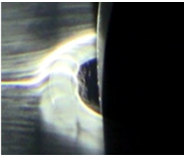
2.2.2. Dye Visualization Systems:
This system also provides a visual means to inspect flow streaklines for the identification of coherent flow structures in the flow. We have a 6-colour dye well available.2.3. Pressure Measurement Capabilities:
We have 16-port (Scanivalve DSA3217) as well as several single-port (Omega PX409) pressure transducers to conduct steady surface pressure measurements.2.4. Constant Temperature Anemometry (CTA):
These systems are used to measure velocity fluctuations at a single point in the flow, which then are used to conduct accurate spectral analyses. We have multiple hot film anemometry probes with adequate signal processing equipment.2.5. Motorized Traverse Systems:
The lab has several motorized linear and rotary traverse systems along with all the necessary hardware and software to generate controlled motion of models wherever needed.2.6. Data Acquisition and Processing Units:
We have several data acquisition and processing computers with all the necessary hardware and software.2.7. Acoustic Measurement Systems:
We have the capability to make acoustic measurements using surface microphones mounted on a model body. In this category, currently, we are working on adding further capabilities into our depository of equipments.2.8. Model Design and Manufacturing Capabilities:
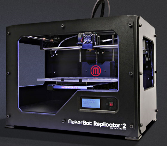
We have a 3D printing facility that enables easy and fast manufacturing of the models to be tested. The CAD designs of the test models to be printed are also made in house. The facility can print a maximum of 28.5 cm X 15.3 cm X 15.5 cm volume with 100-micron layer resolution.