Optimal Orientation of Orthotropic Material for Maximizing Band Gaps
Research by Dane Haystead
| As the use of carbon fiber reinforced plastics (CFRP) increases in aerospace structures it is important to use this material in an efficient manner such that both the weight and cost of the structure are minimized. In some cases these structures may have undesirable vibrational characteristics while also being geometrically constrained, creating a unique problem. One possible solution is to take advantage of the orthotropic properties of composite materials and use it to modify the vibrational characteristics. To accomplish this, research has been conducted into the use of optimization to determine the optimal fiber orientations for maximizing specific eigenfrequencies and frequency (band) gaps of thin rectangular composite plates. |
 A gradient-based optimization scheme is used in conjunction with finite element analysis to determine the optimal fibre orientations throughout a single ply. The single layer is modelled using four-noded orthotropic plate elements with three degrees of freedom per node, with each element having a corresponding fibre angle. The optimization of the fibre angles is an iterative process and the current scheme used is the steepest descent method. The basic process behind gradient-based optimization is to calculate the descent (or ascent, in the case of maximizing the objective function) direction, which is determined from the gradient, then the design variables are shifted along this direction by a specific value, the step size, which is found using a line search method. This is performed iteratively until the specified convergence criteria are met. The design variables in this case are the fibre angles, and the objective function to be maximized can be either the eigenfrequency or the distance between two eigenfrequencies. The gradients are calculated using the finite difference method.
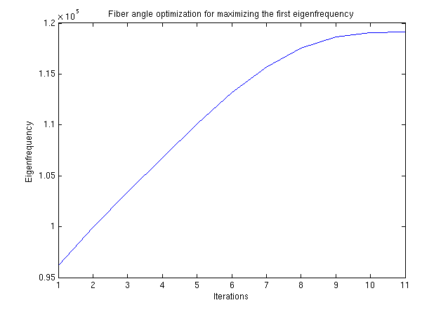 With the optimized ply calculated, it can be inserted into a conventional symmetric composite layup to determine the expected vibrational characteristics. This is performed using a combination of finite element methods (FEM) and composite lamination theory (CLT). CLT is used to calculate the bending and shear matrices for each element which are then inserted into the global stiffness matrix for the FEM calculations. The results are then verified using other calculation methods. With the optimized ply calculated, it can be inserted into a conventional symmetric composite layup to determine the expected vibrational characteristics. This is performed using a combination of finite element methods (FEM) and composite lamination theory (CLT). CLT is used to calculate the bending and shear matrices for each element which are then inserted into the global stiffness matrix for the FEM calculations. The results are then verified using other calculation methods.
|
| Both analytical calculations and commercial software are used to verify the optimization calculations before progressing to the physical testing stage. This is to ensure that the optimization results are reasonable before fabricating the test specimens for modal analysis. The commercial software to be used is ABAQUS. |
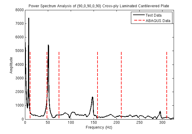 To validate the results of the numerical calculations, specimens will be constructed from unidirectional prepreg carbon fibre tape and subjected to modal testing. This involves measuring the response of the composite plate from an impulse that excites all of its relevant modes of vibration. Accelerometers are used to measure the response and an impact hammer is used to provide the impulse. The data from the tests is recorded and analyzed using commercial software. The figure below is an example of the comparison between the theoretical and experimental results for a cantilevered plate.
|
23 September 2011 - Dane Haystead